| Elapsed time | Variation | Time | Date | Comment | |
|---|---|---|---|---|---|
 |
|||||
| Elapsed time | Variation | Time | Date | Comment | |
|---|---|---|---|---|---|
|
|||||
eStopwatch.net provides you with a simple and free stopwatch. Stop looking for devices to measure time — your stopwatch is now just one click away!
If you have advanced needs, you can save several measurements while stopping the stopwatch or not. You can add other data including date, time, variation and comments.
Finally, you can export everything and manage the data in your favorite spreadsheet.
Have a great time with your online stopwatch!
Use CTRL+C to copy data to your clipboard, then CTRL+V to paste data to your spreadsheet.
This window summarizes two measures types : gray for split time and black for stopped time.
The cross button delete the line and text field is for comments.
Additional information like date and time are available with the "+/-" button.
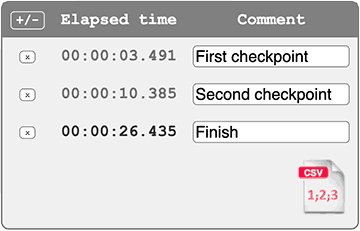
By clicking the CSV icon, you'll obtain a screen export of your data.
Just use CTRL+C to copy data to clipboard. Then you could paste data to your favorite spreadsheet with CTRL+V.
Finding a specific schematic for an APCB M3 94V-0 board can be a challenge because "94V-0" is actually a flammability rating (UL standard) rather than a specific model number, and "APCB" is a large-scale PCB manufacturer that produces boards for dozens of brands like Acer, ASUS, and HP.
However, if you are looking to install, repair, or wire this board, APCB M3 94V-0 Schematic and Installation Guide 1. Identifying Your Actual Board Model
To find a schematic, you need the Model Identifier, not the flammability code. Look for printed text on the silk-screen (usually white or gold ink) that looks like this:
For Laptops: Look for codes like DA0ZRCMB6C0 or compal PALW0.
For Industrial/Control Boards: Look for a string starting with the brand name followed by a series of numbers (e.g., M3-XXXX).
Search for that specific string along with "schematic PDF" or "boardview" to get the exact electrical map. 2. Understanding the 94V-0 Label
When you see 94V-0 on your APCB board, it indicates that the plastic substrate of the PCB is self-extinguishing within 10 seconds during a fire test. While this confirms the board's build quality, it doesn't tell you where the 19V rail or the ground pins are located. Always reference the brand-specific model number for wiring. 3. General Installation Steps
If you are replacing an APCB M3 board or installing it into a new chassis, follow these critical steps: A. Pre-Installation Inspection
Check for Shorts: Use a multimeter in continuity mode to ensure the DC-in jack isn't shorted to ground.
Visual Check: Look for "scorched" components near the 94V-0 marking, as APCB boards often house power delivery circuits in that area. B. Mounting the Board
Standoff Alignment: Ensure every brass standoff in your case aligns with a hole on the PCB. A misplaced standoff touching the traces of an APCB board can cause an immediate short circuit.
Static Safety: These boards are highly sensitive to ESD (Electrostatic Discharge). Use an anti-static wrist strap. C. Power and Data Connections apcb m3 94v0 schematic install
The DC Jack: Most APCB-manufactured laptop boards use a harness-style power connector. Ensure the pins are seated fully; a loose fit can melt the plastic connector.
LVDS/EDP Cable: If this is a display board, the ribbon cable is fragile. Never plug or unplug this while the battery or power adapter is connected, or you risk blowing the backlight fuse. 4. Common Troubleshooting for APCB Boards If the board fails to "post" after installation:
CMOS Reset: Remove the coin-cell battery for 30 seconds to reset the BIOS/UEFI.
Power Rail Check: Without a schematic, you can usually find the "Main Rail" by testing the large grey inductors (coils) near the CPU/GPU. They should show low resistance but not 0 ohms.
Bios Flash: APCB boards are known to have "corruptible" BIOS chips. If the hardware looks fine but there’s no display, re-flashing the BIOS chip often solves the issue. 5. Where to Download Schematics
Since APCB is an OEM, they do not release schematics to the public. You will need to visit technician forums such as: BadCaps.net VinaFix Bios-Mods
Search these sites using the Model Identifier you found in Step 1.
Note: Working on PCBs requires advanced soldering skills. If you are looking for the schematic to perform a "bypass," ensure you have a regulated DC power supply to limit current and prevent blowing the inner layers of the board.
Do you have the brand name or any other longer strings of numbers printed on the green or blue part of the board?
Title: Understanding the "APCB M3 94V0" Reference for Schematic & Installation
If you are working with a board marked "APCB M3 94V0," you are likely handling a custom or OEM-specific printed circuit board (PCB). Here is a breakdown of what these markings mean and how to approach the schematic installation process. Finding a specific schematic for an APCB M3
1. Decoding the Markings
2. The "Schematic Install" – What It Means Unlike software, you do not "install" a schematic onto a PCB. In an electronics context, "schematic install" usually refers to one of the following:
3. How to Proceed: Finding and Using the Schematic
Step A: Identify the Host Device The APCB M3 board is likely a sub-assembly inside a larger product (e.g., a Samsung monitor, a Dell power supply, or a Chinese CNC controller). Look for a main brand logo or FCC ID on the board.
Step B: Locate the Schematic File
Step C: Installing the Schematic into Your EDA Tool (if you have the file)
.SchDoc, .DSN, .pdf).File > Open or Import to load the schematic.Design > Update PCB Document command to push the schematic netlist to the board.Step D: Physical Installation (If you meant mounting the board) If your goal is to install the physical APCB M3 board into a system:
Important Safety Note (94V0 Reminder): While the APCB M3 board uses 94V0-rated flame-retardant material, this does not make it immune to electrical fires. Always follow the schematic’s specified current limits, use a current-limited power supply during testing, and never bypass fuses.
Conclusion "APCB M3 94V0 schematic install" is not a standard procedure. You must first identify the host device, locate the correct schematic document (often a PDF), and then either view it for manual wiring or import it into PCB design software. If you are attempting to reverse-engineer the board, the 94V0 rating assures you that the board material is safe to solder and handle under normal conditions.
APCB M3 94V-0 is not a single product but rather a marking often found on NVIDIA GeForce 310
(512MB) low-profile graphics cards. The text "94V-0" is a safety certification from Underwriters Laboratories (UL) Title: Understanding the "APCB M3 94V0" Reference for
, indicating the circuit board material is flame-retardant and will self-extinguish within 10 seconds. Alibaba.com Understanding the Markings The manufacturer of the printed circuit board (PCB).
Likely a specific material or manufacturing standard/model used by the factory. A critical fire safety rating. Alibaba.com Schematic and Repair Resources
Because this marking is a generic manufacturing label, a specific "install schematic" for just "APCB M3 94V-0" does not exist. You must search for the schematic based on the (e.g., NVIDIA GeForce 310) or the Assembly/Part Number
found on a separate sticker (often starting with "P/N" or "600-").
For general motherboard or graphics card repair steps, you can refer to these types of guides:
Technical Report: Analysis of APCB M3 94V0 Schematic Installation and Integration
Date: October 26, 2023 Subject: Installation Guidelines and Schematic Interpretation for APCB M3 94V0 Motherboards
Installing and maintaining an APCB M3 94V0 schematic board requires a methodical approach to identifying input/output pins in the absence of official documentation. The 94V0 rating ensures the board is constructed from flame-retardant material suitable for standard electronics enclosures. By following the identification methods and safety protocols outlined in this report, technicians can safely integrate these boards into power supply applications.
Using your schematic, identify the B– (battery negative) and B+ (battery positive) pads, plus intermediate balance pads.
Critical: Solder balance wires in order from B0 to highest Bx. Double-check each voltage before soldering – reversed balance lead = dead IC.